Easily make a Continuity Tester at Home(Circuit Diagram)
Hey, in this article, we are going to see the circuit diagram for making a continuity tester at home. This circuit diagram of continuity tester will help you to understand the circuit connection, component requirement, and its working principle.
A continuity tester is a very simple device that is used to determine if an electrical path exists between two points in a circuit. Making your own continuity tester at home not only saves money but also provides an opportunity to practically understand the basics of electronics. So, in this guide, we will go through the process of building a simple continuity tester using easily accessible components. We can make it in such a way that it will emit a sound and light signal when it detects continuity, indicating that the circuit is complete or there is no broken, faulty, or very high resistive path.
Component List
Here is the below component list to make a simple continuity tester.
- BC547 Transistor - 1 PCs
- 100 Ohm Resistor - 2 PCs
- LED (Red Color) - 1 PCs
- Buzzer - 1 PCs
- 3.7V Battery - 1 PCs
- Probes - Red for Positive, Black for Negative
- Wires
Circuit Diagram
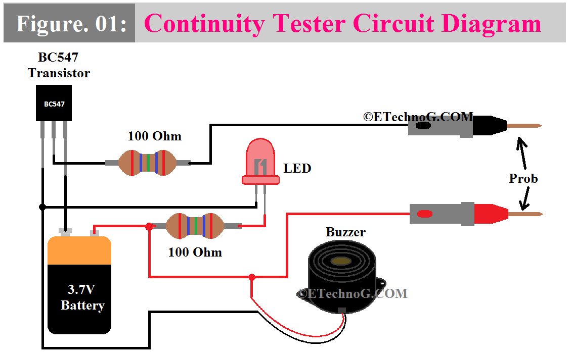
Here, you can see a simple Continuity Tester circuit diagram below.
Connection Description
- Connect the Positive terminal of the battery directly to the positive terminal of the buzzer, positive probe, and the positive terminal of the LED in series with the 100 Ohm resistor.
- Connect the negative terminal of the battery to the emitter terminal of the BC547 Transistor.
- Connect the collector terminal of the BC547 Transistor to the negative terminal of the LED and Buzzer.
- Connect the Base terminal of the transistor BC547 to the Negative Probe in series with a 100 Ohm Resistor.
Working Principle
In the above circuit, the BC547 transistor acts as a switch in this circuit. When a small current flows from the base (B) to the emitter (E), it allows a larger current to flow from the collector (C) to the emitter (E).
Here the 100 Ohm resistors are used to limit the current flowing through the LED and Base Terminal of the Transistor. They ensure that the LED and Transistor receive a safe amount of current without being damaged.
Here, the LED (Light Emitting Diode) is used as a visual indicator in the continuity tester. When there is continuity in the circuit being tested which means electricity can flow through it without interruption, the LED lights up. It indicates that the circuit is complete.
Here, the buzzer is an audible indicator in the continuity tester. Similar to the LED, it activates when continuity is detected in the circuit being tested. It emits a sound to signal that the circuit is complete and electricity can flow through it.
Here, the 3.7V battery serves as the power source for the continuity tester. It provides the necessary voltage to power the circuit and enable the LED and buzzer to function.
Here the probes are used to make electrical connections with the circuit being tested. The red probe is connected to the positive terminal of the battery, while the black probe is connected to the negative terminal. When the probes are touched to different points in a circuit, they allow the flow of electricity to be tested.
Now coming to the Actual Working Principle,
When the red probe is touched to the positive terminal of a circuit, and the black probe is touched to the negative terminal, current will flow from the positive terminal of the battery through the circuit being tested, through the LED and buzzer (if continuity exists), and back to the negative terminal of the battery.
If there is a continuity in the circuit being tested which means the electrical path is complete and unbroken, a small current will flow through the base of the transistor which will turn it on. Once the transistor gets turned On, a larger current will flow from the collector to the emitter of the transistor which activates both the LED and the buzzer.
As a result, the LED lights up, providing a visual indication of continuity, and the buzzer emits a sound, providing an audible indication. If there is no continuity in the circuit being tested, the LED remains off, and the buzzer stays silent, indicating an interrupted circuit.
See Also:
Easily make a Continuity Tester at Home(Circuit Diagram)
 Reviewed by Author
on
April 10, 2024
Rating:
 Reviewed by Author
on
April 10, 2024
Rating:

