Push Button Switch Wiring Diagram and Connection Procedure
Hi, in this article, we are going to see and learn both the NO and NC push button switch wiring diagrams and connection procedures. A push button switch is also known simply as a push button or push switch. It is a type of switch that is activated by pushing it. These switches are commonly used in various electrical circuits, electronic devices, appliances, and control panels to control power or functions. There are basically two types of push-button switches - Momentary push button switch and Latching push button switch.
The Momentary push button switch is spring-loaded and returns to its original position when released. It is typically used for temporary activation, such as turning a device on or off or electrical control panels. Unlike momentary switches, Latching push button switches stay in their toggled position until they are pushed again to change state. They are generally used for applications where a permanent change in state is desired, such as switching between different modes or settings. Anyway, in this article, we are going to see the connection of the Momentary push button that is mostly used in electrical control panels.
Wiring Diagram
There are basically two types of Momentary push button switches that are used in electrical control panels - NO and NC.
"NO" stands for Normally Open, and "NC" stands for Normally Closed. These terms describe the default state of the contacts within the switch when it is not pressed.
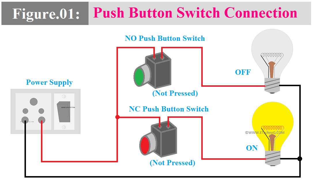
NO Push Button Switch: In a NO push button switch, the contacts are open (disconnected) when the button is not pressed or actuated. Pressing the button closes (connects) the contacts and it allows current to flow through the switch.
NC Push Button Switch: In an NC push button switch, the contacts are closed (connected) when the button is not pressed or actuated. When the button is pressed the contacts get open and interrupt the flow of current.
Here, in the above figure, we have shown the connection of both NO and NC push button switches. Here, you can see both of the switches are not pressed. So the lamp connected to the NO push button switch is not glowing and the lamp connected to the NC push button switch is glowing.
Now, in the below figure, you can see both the NC and NO push button switches are pressed. So the lamp connected to the NO push button switch is now glowing and it will continuously glow until the switch is unpressed or released. On the other hand, the lamp connected to the NC push button switch is now turned off and it will remain turned off until the switch is unpressed or released.
Connection Procedure
The connection procedure for a NO (Normally Open) and NC (Normally Closed) push button switch depends on the specific application and how you want the switch to function within the circuit. Anyway, here I have explained the general connection procedure to explain how actually the push button switches are connected.
Normally Open(NO) Push Button Switch Connection:
- Connect one terminal of your power source (e.g., battery, power supply) to one terminal of the load (e.g., a light bulb, motor) you want to control.
- Connect the other terminal of the load to the common terminal (COM) of the NO push button switch.
- Connect the NO (Normally Open) terminal of the push button switch to the remaining terminal of your power source.
- When the push button switch is not pressed, the circuit remains open, and no current flows through the load. Pressing the button closes the circuit, allowing current to flow and activating the load.
Normally Closed(NC) Push Button Switch Connection:
- Connect one terminal of your power source to one terminal of the load you want to control.
- Connect the NC (Normally Closed) terminal of the push button switch to the remaining terminal of the load.
- Connect the common terminal (COM) of the NC push button switch to the other terminal of your power source.
- When the push button switch is not pressed, the circuit is closed, and current flows through the load. Pressing the button opens the circuit, interrupting the flow of current and deactivating the load.
Push Button Switch Connection with Contactor
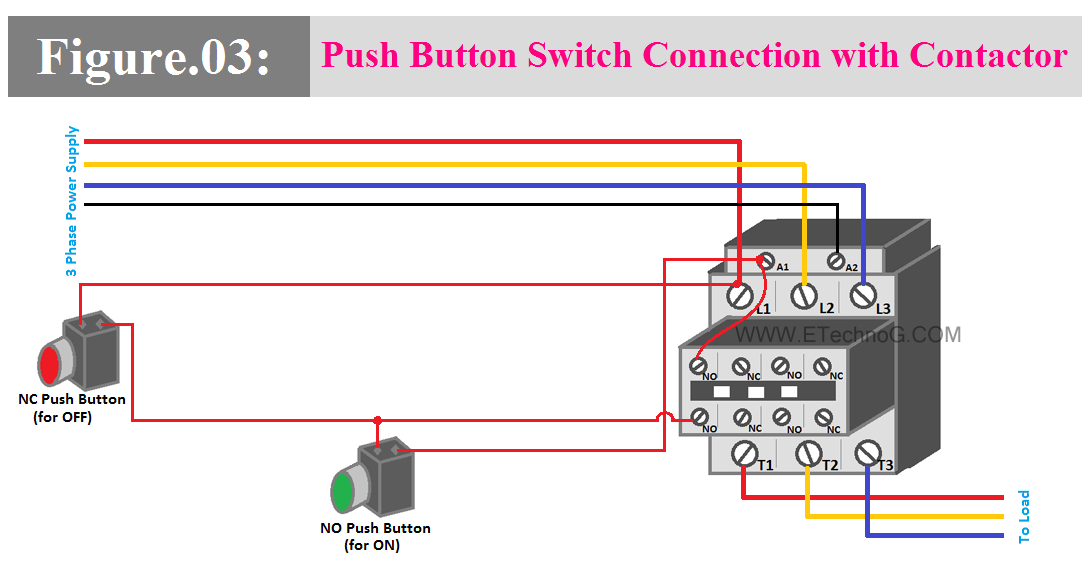
Push button switches and contactor connections are used in various electrical control applications, especially in industrial sectors where remote or manual control of electric motors, lighting, or other loads is required. So here in the below wiring diagram, I have shown the connection between NO and NC push button switches with a contactor. It will help you deeply understand the connection and operation of NO and NC push button switches.
Here, Pressing the NO push button switch will energize the contactor coil, closing the contacts and allowing current to flow to the load, turning it on. Once the contactor is energized, the NO contacts of the contactor will become NC and it will act as a holding contact, maintaining the contactor's state even after the NO push button switch is released. Now Pressing the NC push button switch will de-energize the contactor coil as it breaks the path for current flow to the contactor coil. The contactor will remain off until again the NO push button switch is pressed.
Read Also:
Push Button Switch Wiring Diagram and Connection Procedure
 Reviewed by Author
on
April 10, 2024
Rating:
 Reviewed by Author
on
April 10, 2024
Rating:


