Smoke Detector Circuit Diagram and Connection for Domestic Use
Hey, in this article we are going to see a very simple smoke detector circuit diagram. It can be used for domestic purposes such as in homes for detecting domestic gas leakages such as alcohol, methane, LPG, hydrogen, NH3(ammonia), Carbon monoxide, Benzene, propane, and smoke. Sometimes burning happens without any flame. In this case, the heat detector will be failed to detect but the smoke detector can detect it due produced smoke. Here, we have used an MQ2 Gas sensor with the LM358 IC to build this circuit. This circuit needs very few electronic components and it can be operated with a 6V DC power source. So you can use it with a 6V battery also.
Components Required
- IC LM358 - 1 PCs
- MQ2 Gas Sensor - 1 PCs
- 10K Preset - 1 PCs
- 6V Buzzer - 1 PCs
- Ceramic Capacitor 0.1uF - 1 PCs
- LED Green Color - 1 PCs, Red Color - 1 PCs
- Resistor 10 Kilo Ohm - 1 PCs, 100 Ohm - 2 PCs
- 6V DC Power Supply
Circuit Diagram
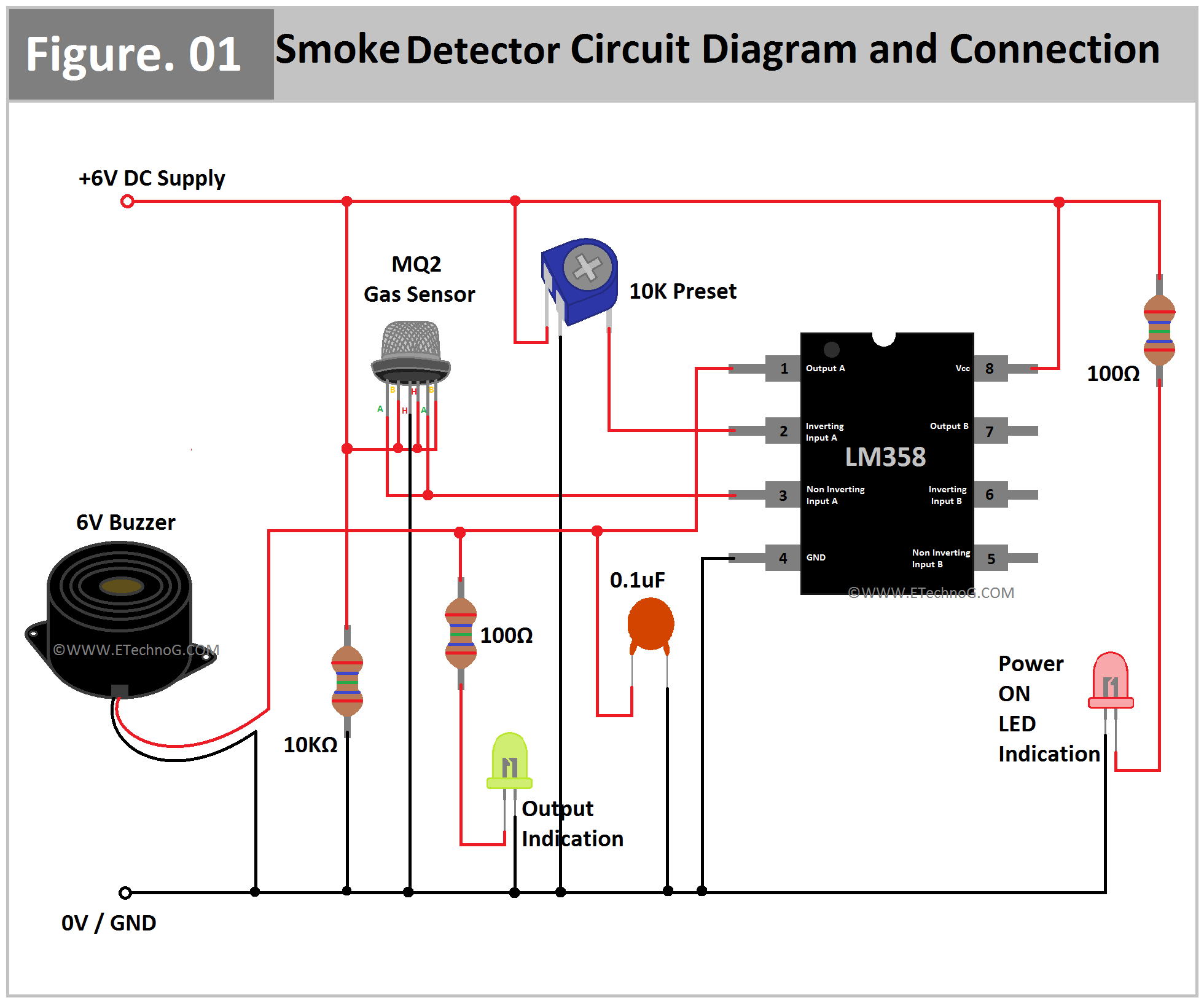
Here, you can see the Smoke Detector Circuit Diagram and the connection between each component.
Connection Procedure
- Connect Pin No 8(Vcc) of the IC LM358 to the positive terminal of the power source.
- Connect Pin No 4(Ground) of the IC LM358 to the negative terminal of the power source.
- Connect the negative terminal of the Buzzer to the negative terminal of the power source.
- Connect the positive terminal of the Buzzer to Pin No 1(Output A) of the IC LM358.
- Connect a 0.1uF Ceramic Capacitor between Pin No 1(Output A) of the IC LM358 and the negative terminal of the power source.
- Connect a green color LED in series with a 100 Ohm resistor between Pin No 1(Output A) of the IC LM358 and the negative terminal of the power source.
- Connect a red color LED in series with a 100 Ohm resistor between the positive and negative terminal of the power source.
- Connect the B, H, and B terminals of the MQ2 Smoke sensor together and then connect it to the positive terminal of the power source.
- Also, connect that joint to the negative terminal of the power source in series with a 10 Kilo Ohm Resistor.
- Connect both A terminals of the MQ2 Sensor to each other and then connect to Pin No 3(Non-Inverting Input A) of the IC LM358.
- Connect the rest H terminal of the MQ2 sensor to the negative terminal of the power source.
- Connect the power terminal of the Preset to the positive terminal of the power source.
- Connect the ground terminal of the preset to the negative terminal of the power source.
- Connect the output terminal of the preset to Pin No 2(Inverting Input A) of the IC LM358.
Operation and Working Principle
Basically, the LM358 is an operational amplifier IC and in this case, it acts as a comparator. It compares the voltage between its Inverting and Non-Inverting input Terminals. Using the preset we set a voltage(or we can say it as sensitivity) at its inverting input terminal. And the smoke sensor maintains a voltage to the non-inverting terminal. So when the smoke sensor senses the smoke the voltage across the non-inverting terminal also varied and the LM358 IC generates an output signal to activate the buzzer.
Read Also:
Thank you for visiting the website. keep visiting for more updates.
Smoke Detector Circuit Diagram and Connection for Domestic Use
 Reviewed by Author
on
April 25, 2023
Rating:
 Reviewed by Author
on
April 25, 2023
Rating:

