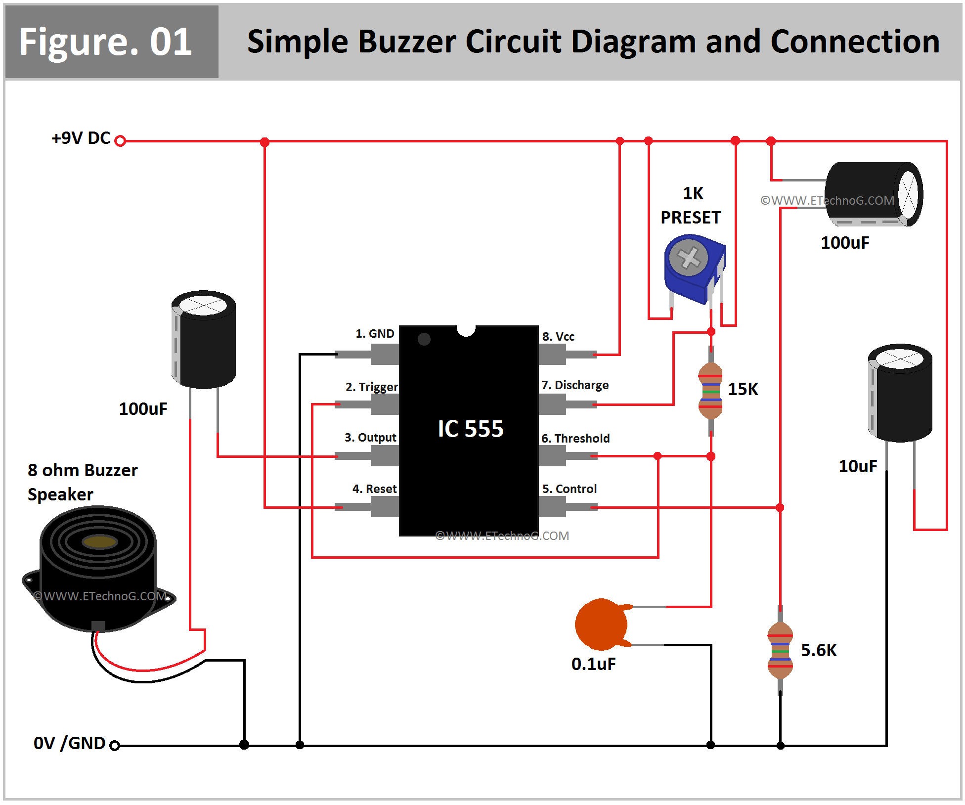
Simple Buzzer Circuit Diagram and Connection using IC 555
Here, in this article, we are going to see a very simple Buzzer Circuit Diagram with IC 555. Buzzers are used in homes, offices, plants, farms, etc for alarming purposes. Even you can build this circuit as your electronic project with 555 IC. You can portray the practical application of 555IC. This circuit is operated with a 9V DC power supply so you can use it with a 9V battery that will make this portable device. The main function of this circuit is to drive the speaker for a short time duration. Using different component values we can get some different patterns also. Here, in this circuit, a Preset is used. So by varying the Preset value, we can set a different time delay for the speaker output.
Components Required
- 555 IC – 1 No
- 9V, 8 Ohm Buzzer Speaker – 1 No
- 1K Preset or Variable Resistor – 1 No
- Electrolytic Capacitor 100uF – 2 Nos, 10uF – 1 No
- Ceramic Capacitor 0.1uF – 1 No
- Resistor 15 Kilo Ohm – 1 No, 5.6 Kilo Ohm – 1 No
- 9V DC Power Source
Circuit Diagram
Here, you can see the Buzzer Circuit Diagram using IC 555 and the connection between internal components.
Connection Procedure
- Connect Pin No 1(Ground) of the IC 555 to the negative terminal of the power source.
- Connect Pin No 4(Reset) and Pin No 8(Vcc) to the positive terminal of the power source.
- Connect the Negative terminal of the Buzzer Speaker to the negative terminal of the power source.
- Connect the positive terminal of the buzzer speaker to the Pin No 3(Output) of the IC 555 in series with a 100uF Electrolytic Capacitor.
- Connect Pin No 5(Control) of the IC 555 to the positive terminal of the power source in series with a 100uF Electrolytic Capacitor.
- Also, connect Pin No 5(Control) of the IC 555 to the negative terminal of the power source in series with a 5.6 Kilo Ohm Resistor.
- Connect the Output and Power terminals of the 1K Preset to the positive terminal of the power source.
- Connect the Ground Terminal of the 1K Preset to the Pin No 7(Discharge) of the IC 555.
- Also, connect Pin No 7(Discharge) of the IC 555 to Pin No 6(Threshold) in series with a 15 Kilo Ohm resistor.
- Connect Pin No 2(Trigger) and Pin No 6(Threshold) of the IC 555 together and then connect it to the negative terminal of the power source in series with a 0.1uF ceramic capacitor.
- Connect a 10uF Electrolytic Capacitor across the positive and negative terminals of the whole circuit.
Operation and Working Principle
We know that the IC 555 can produce oscillating signals or time delay signals. And the time delay interval can be controlled by an RC network in the Monostable Mode. So here, the IC 555 is used to produce the square wave oscillating signal that will drive the speaker. When we power up the circuit the buzzer speaker will produce an audible square wave tone. And the series combination of preset and ceramic capacitors makes the RC network. So when we rotate the knob of the preset time delay of the output signal from the IC 555 also be varied so the speaker sound also is varied.
Read Also:
Thank you for visiting the website. keep visiting for more updates.
Simple Buzzer Circuit Diagram and Connection using IC 555
 Reviewed by Author
on
April 25, 2023
Rating:
 Reviewed by Author
on
April 25, 2023
Rating:

