Automatic Headlight Circuit Diagram and Connection
Hey, in this article, we are going to see the Automatic Headlight Circuit Diagram and its connection procedure. Automatic headlights are not different than any other headlights you see at the front of any car. Just the difference is when the car is on and it is dark it will activate automatically without the driver needing to press a manual switch. The automatic headlights in the car also can be turned on or off manually by the driver if they want. If the driver selects the headlight controls to run as automatic like default by keeping the switch in ‘auto position, then this system will smartly take care of this job for the driver.
Automatic Headlight systems are mostly used in modern luxurious vehicles where the headlight is automatically controlled by detecting the brightness of the outside of the vehicle. Generally, an illumination sensor is installed in the vehicle that helps to detect the illumination level. The headlight will be automatically turned on when the illumination level drops below a certain level and the headlight will be automatically turned off when the illumination level rises above a certain level.
Anyway, you can easily make an automatic headlight circuit for use anywhere. So, here we have given a very simple circuit diagram that will help you to make a homemade Automatic Headlight system.
Circuit Diagram
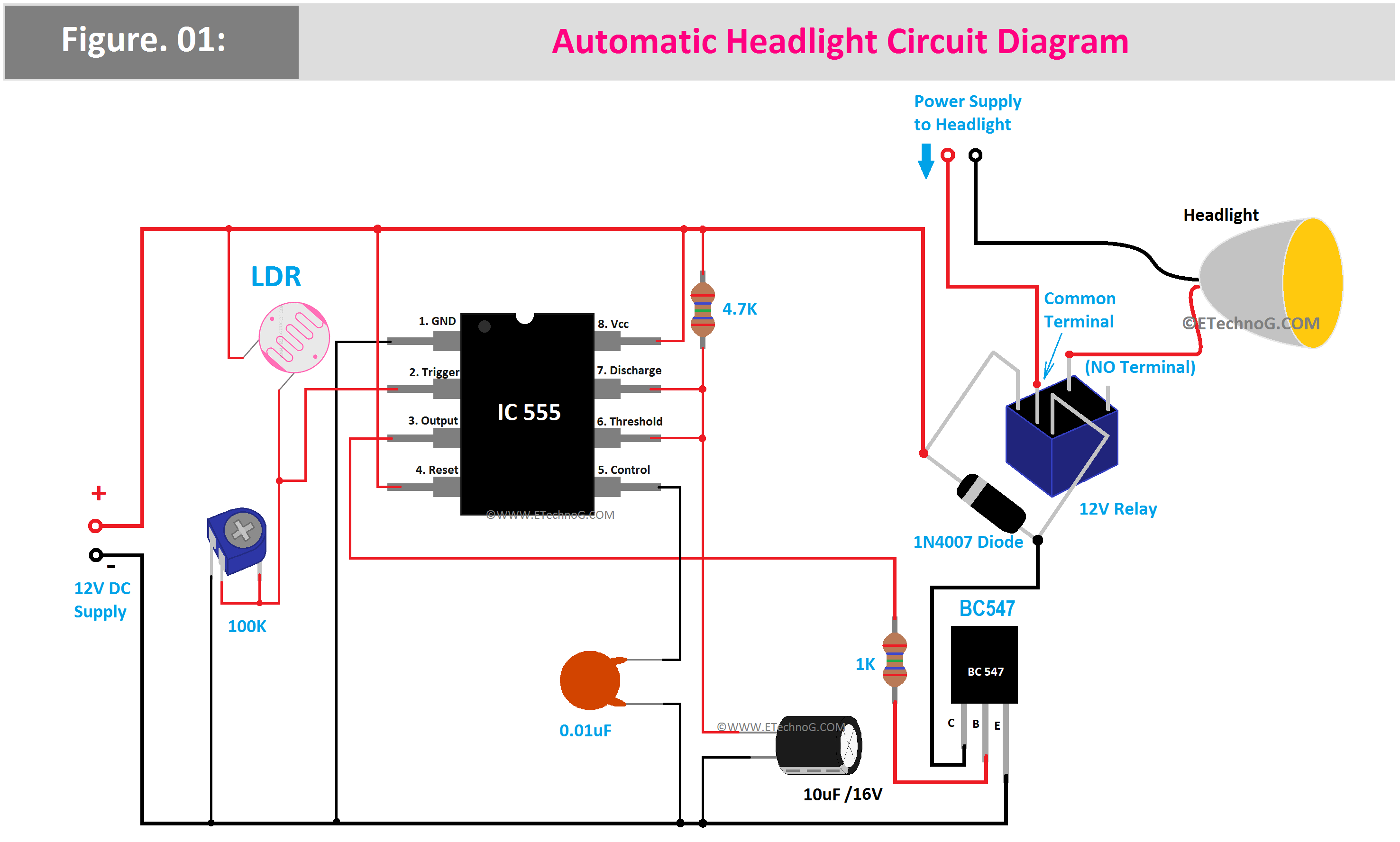
Here, you can see the circuit diagram of Automatic Headlight.
Component List
- 12V DC Relay - 1 PCs
- 1N4007 Diode - 1 PCs
- BC547 Transistor - 1 PCs
- 1K Resistor - 1 PCs
- 4.7K Resistor - 1 PCs
- 10uF, 16V Electrolytic Capacitor - 1 PCs
- 0.01uF Ceramic Capacitor - 1 PCs
- LDR - 1 PCs
- 100K Preset - 1 PCs
- IC 555 - 1 PCs
Connection Description
- The LDR is connected to the trigger terminal of the IC 555 with a 100K Preset.
- The Control terminal of the IC 555 is connected to the ground in series with a 0.01uF ceramic capacitor.
- The Discharge and threshold terminals of the IC 555 are connected to the positive supply in series with a 4.7K resistor and to the ground in series with a 10uF electrolytic capacitor.
- The Output of the IC 555 is connected to the base terminal of the BC 547 Transistor in series with a 1K resistor.
- The coil of the 12V Relay is connected across the power supply in series with the collector terminal of the BC 547 Transistor.
- The 1N4007 Diode is connected in reverse bias across the Relay Coi.
- The Headlight is connected to a different power supply through the Normally Open(NO) terminal of the Relay.
Working Principle
The working principle of the Automatic Headlight system is very simple. When the LDR detects the darkness level it will activate the IC 555. The IC 555 will activate the BC 547 Transistor. Once the BC 547 Transistor is activated the Relay also be activated so the Headlight will be turned On. When the LDR detects the illumination the reverse operation happens in the circuit and the Headlight will be turned Off. Here, the 100K preset is used to adjust or set the illumination level at which the headlight will turned Off or turned On.
Automatic Headlight Circuit Diagram and Connection
 Reviewed by Author
on
February 11, 2024
Rating:
 Reviewed by Author
on
February 11, 2024
Rating:

