Air Cooler Internal Circuit, Wiring Diagram, and Connection
Hey, in this article we are going to see the internal circuit or wiring diagram of an Air Cooler. Air Cooler is a device that is used for cooling inside a room by increasing the airflow and spreading the water particles. Air coolers are cheaper than air conditioning systems which is why most people prefer to use an air cooler than an air conditioning system. An Air Cooler is built with some electrical machines, devices, and electrical circuitries. If you are an electrical technician and want to repair an air cooler first of all you must know its internal wiring otherwise you can not able to repair or identify the fault.
Air Cooler Internal Wiring Diagram
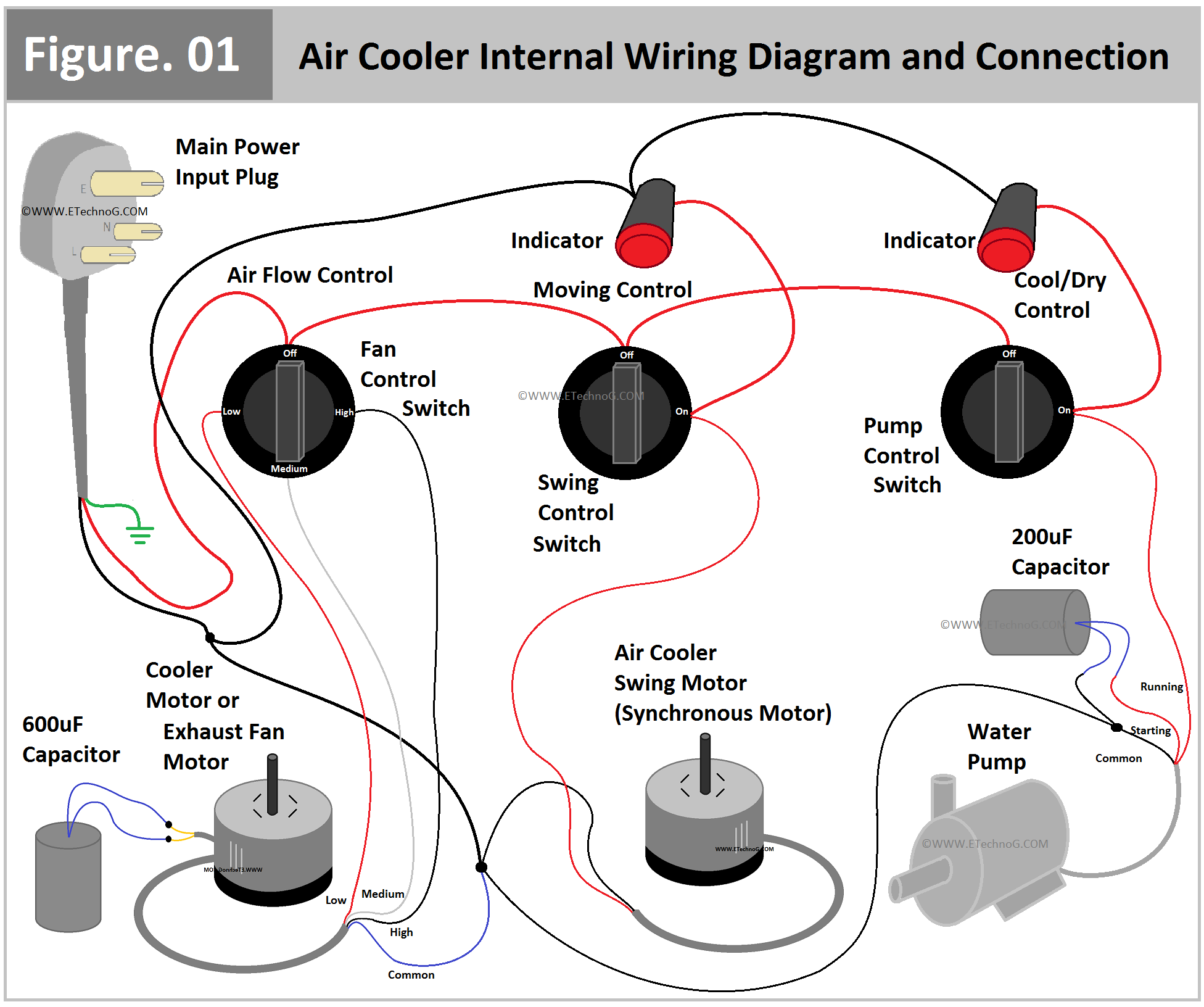
Here you can see the internal circuit of an air cooler and the connection between each component.
Air Cooler Internal Components
An Air Cooler has the following internal components and their functions,
Cooler Motor or Exhaust Fan
Generally, a single-phase induction motor is used for cooling. The main function of this fan is to circulate the airflow. It is a capacitor start-capacitor-run motor so a capacitor needs to connect to it. It has three terminals for different speeds - High, Low, and Medium. We can control the speed of this motor by connecting different terminals to the power supply through a selective or rotary switch.
Swing Motor
Generally, and single-phase synchronous motor is used as a swing motor. It does not need to connect with a capacitor for its start. The main function of this swing motor is to move the airflow unit to change the airflow direction.
Water Pump
Here, also a single-phase induction motor is used for the water pump. It is used to pump the water from the water tank to spread out to the airflow. It also needs a capacitor for starting.
Capacitors
Generally, a 600uF to 800uF Capacitor is used for the cooling fan motor, and a 200uF to 400uF capacitor is used for the water pump motor.
Switches
Generally, rotary-type selective switches are used to control the cooling fan, swing motor, and water pump. The 3-way rotary type selective switch is used for the cooling fan that provides three switching functions for Low, Medium, and High Speed. One way, rotary switches are used for the other two motors.
Indicators
Here, two indicator lights are used for swing control and water pump control.
Internal Connection Description
- The phase terminal from the input power plug is connected to the input terminal of all the rotary switches.
- The neutral terminal from the input power plug is connected to the neutral terminal of all the motors and indicator lights.
- The High, Medium, and Low-Speed terminals of the fan motor are connected to the High, Medium, and Low terminals of the 3-way rotary switch.
- The fan motor also has other two terminals for capacitor connection where a 600uF Capacitor is connected.
- The phase terminal of the swing motor is connected to the output terminal of the swing control switch.
- Also, the output terminal of the swing control switch is connected to the swing control indicator light.
- The Running terminal of the water pump motor is connected to the output terminal of the pump control switch.
- Also, the output terminal of the pump control switch is connected to the pump running status indicator or Cool/Dry status indicator light.
- A 200uF capacitor is connected across the starting and neutral terminals of the pump motor.
Operation and Working Principle
When the fan control switch is operated the fan will turn on or turn off or run at different speeds. When the switch is turned to Low the motor will rotate at a low speed, when the switch is turned to Medium the motor will rotate at a medium speed, and when the switch is turned to High the motor will rotate at a high speed. Similarly, the other two motors are can be operated by their respective switches. But the swing motor and water pump motor only run at a single speed when they are turned on.
Read Also:
Thank you for visiting the website. keep visiting for more updates.
Air Cooler Internal Circuit, Wiring Diagram, and Connection
 Reviewed by Author
on
April 25, 2023
Rating:
 Reviewed by Author
on
April 25, 2023
Rating:

